What Is a 3D Elevation Drawing? A Complete Guide for Homeowners and Architects
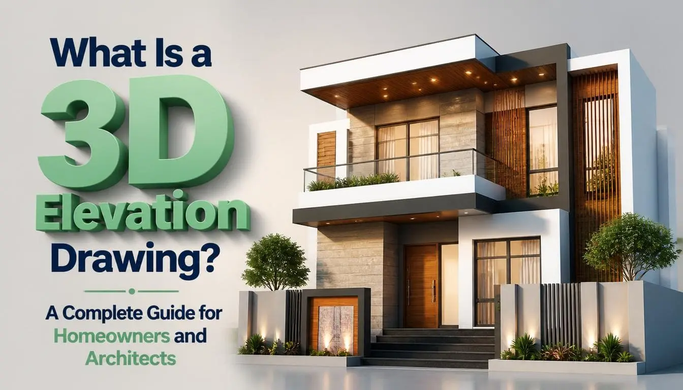
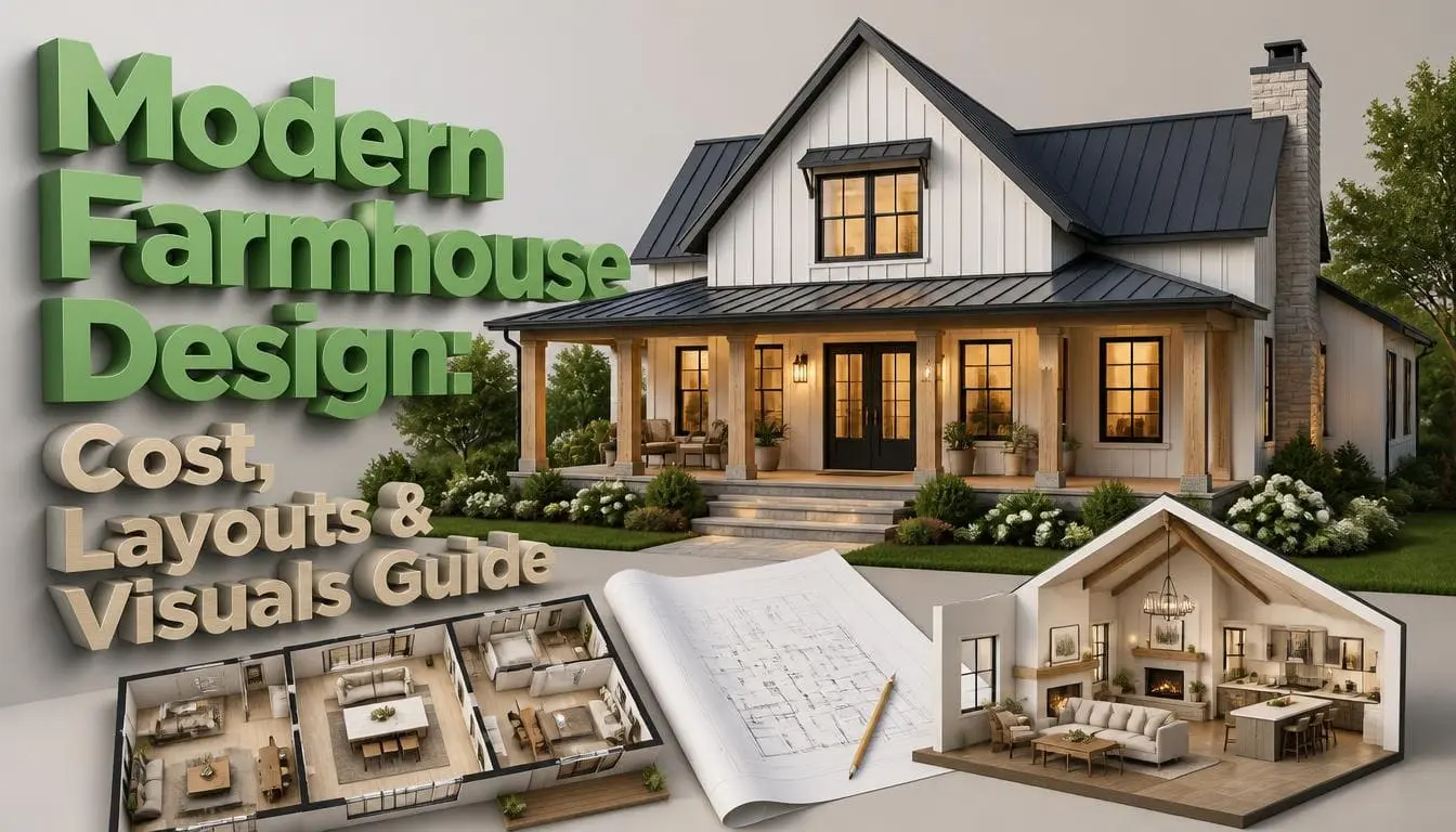
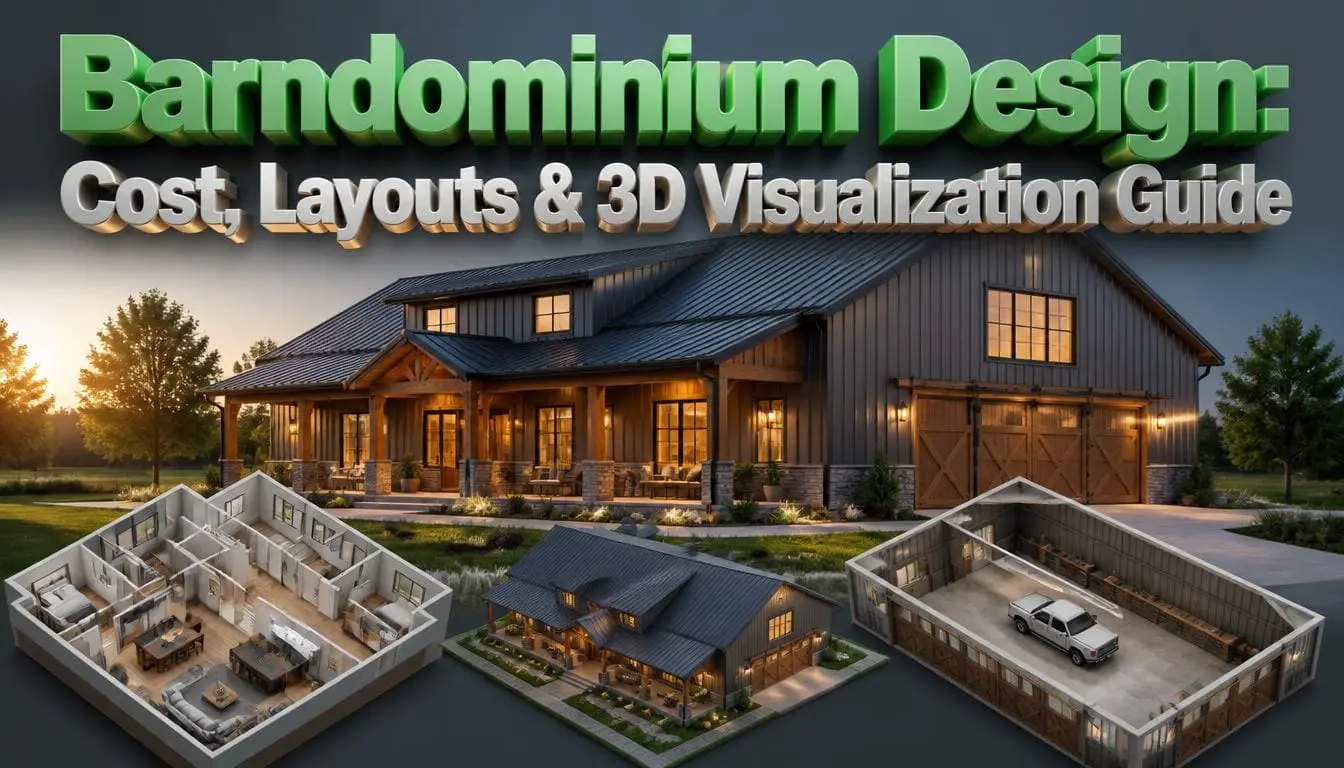
A 3D elevation is a realistic view of the exterior of a building. Each 3D elevation typically shows one face of the building (front, side, or back) in full, realistic detail. This includes lighting, shadows, and depth. Permits and construction require 2D elevations that use simple line drawings. However, a 3D building elevation offers a clear picture to the client and homeowner about what the finished building will look like after construction.
Looking forward to seeing your project in 3D? A 3D building elevation design lets you see your building structure before any construction.
What Is A 3D Building Elevation Drawing?
A 3D view is a realistic, dimensional presentation of one face of a property. It’s based on a 3D architectural drawing. You can see the brick, stucco, glass, or wood siding. It also depicts material finishes, including depth, texture, and shadow, so that the clients can see its true appearance.
After finalizing 2D plans, the designers and architects produce 3D building elevations. The 3D is usually not a construction document; it is a communication document. These are used to assist homeowners, developers, and planning boards to understand a design before construction.
- 3D building elevation is a response to the question “What will this building really look like?“
- 2D elevation is the answer to “What are the actual dimensions/ technical specifications required for construction?”
How Is A 3D Elevation Different From A 2D Elevation Drawing?
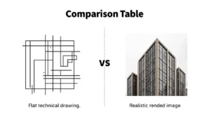
The fundamental distinction is reflected in the purpose and projection technique. 2D Elevation involves an orthographic drawing with no perspective distortions, used for permits and construction purposes. A 3D exterior elevation is a rendered image that has depth, light, and realistic materials, mostly used for design communication.
| Feature | 2D Elevation | 3D Elevation |
| Projection | Technical elevations (flat, no perspective) | Dimensional, often with perspective or realistic shading |
| Primary use | Permits, zoning, construction documents | Client presentations, marketing, design approval |
| Detail shown | Dimensions, line weights, notations | Materials, color, lighting, landscaping, shadow |
| Created by | Architects, drafters (CAD) | Architects, visualization artists, rendering software |
| Required for permits? | Yes, in most jurisdictions | Rarely required, but increasingly requested by clients |
How Do Architectural Section Drawings Work?
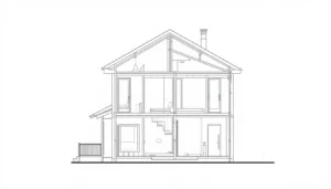
A section drawing works by cutting vertically through the building and showing everything the cut plane passes through, such as:
- Walls
- Floors
- Roof structure
- Ceiling heights
A cross section drawing represents a building from inside by cutting through it vertically. A floor plan represents the horizontal view of a building from above.
In the section view, everything cut by the section plane is shown as a bold line. Anything seen beyond is generally shown with a thinner line. This line-weight convention lets an expert reader instantly tell what’s been sliced through versus what’s simply visible in the background.
Sections are useful because elevations and floor plans cannot show what is hidden. Sections show you what the rooms feel like, and how the building is built, revealing:
- Floor-to-floor heights
- Ceiling volumes
- Roof pitch
- Structural depth
The above features cannot be depicted by a flat elevation. Some projects also use a sectional elevation, which combines an interior cut-through view with the exterior of a building. These are useful for showing how interior design relates to the exterior form in one drawing.
How Do Specific Components (A Window Head, A Stair Rail) Actually Assemble?
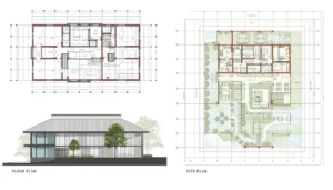
A single project usually needs several drawing types working together, each answering a question the others cannot. Most residential and commercial projects are still documented primarily in CAD or BIM platforms, with 3D renderings layered on top for presentation purposes.
Elevation drawings are the main part of construction documents, with most projects needing at least four elevations. The front elevation design draws the most attention because it is often analyzed first during the process of approval.
As defined by the American Institute of Architects (AIA), elevation drawings are a necessary part of most building permit submission packages in the United States. Planning agents can verify that projects fulfill regional codes before construction starts.
Why The Front Elevation Matters Most
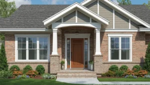
In residential and commercial projects, the most reviewed plan is the front elevation. It is the first impression of planning boards, neighbors, and clients. It reveals the main door and the main level roof. It comprises things such as:
- Window types
- Materials palette
A great deal more attention is devoted to material selection, proportion, window rhythm, and other elements of the front elevation than side and rear elevations. This is included in permit packages, marketing material, and requests for HOA approval.
How Does Elevation Rendering Actually Work?
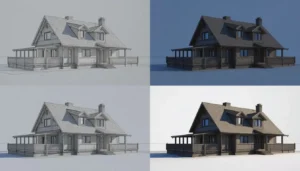
Elevation rendering is the transformation of a 2D elevation and 3D modeling into a realistic structure with materials, lighting, and shadow. This technical step transforms a “3D building elevation” into a visual for presentation.
An overview of the rendering process:
Model the building
The architect produces a digital 3D preview of the structure from 2D plans, which is why having a complete overview of 2D architectural drawings is important before moving into the construction process.
Apply materials and textures
Materials used for brick, siding, stone, glass, and roofing are laid over the surfaces of the model.
Set the light and the times of the day
The sun angle, shadow direction, and ambient light are configured to depict the building.
Add context
The model is surrounded by various elements, including landscaping, driveways, adjacent buildings, and the sky.
Compose a final image
The software performs a light, reflection, and shadow calculation to create a photorealistic still shot or walk-through.
Searching for inspiration first? Exploring different 3D design ideas helps you compare styles, materials, and exterior finishing before finalizing a design.
Key Takeaways
- A 3D building elevation is a rendered and dimensional version of a flat drawing.
- Traditional 2D elevations are just technical projections.
- Elevation visualization is the conversion of a 2D/3D model into realistic images.
- There are three basic categories of drawings used in buildings: floor plans, sections, and elevations.
- Section drawings show the interior of buildings.
- Elevation drawings show the exterior of buildings.
- The typical home project needs 4 elevations, i.e., front, back, and both sides.
Conclusion
A 3D elevation drawing shows a realistic preview of a building’s facade before starting any physical work. Unlike a 2D elevation, it shows the design with materials, lighting, textures, and depth. This makes the final project much easier to visualize. 2D elevations are important for permits and construction documents, but 3D building elevations are great for homeowners, architects, construction, and planning authorities to understand how the building will look when finished. If you are planning to design a new home or renovate an existing one, 2D and 3D building elevations help you see the comprehensive design. Thus, this helps you make sound decisions even before construction begins.
FAQ
Q1: What’s the difference between an elevation and a section?
An elevation shows the outside face of a building looking straight on. A section cuts vertically through the building to reveal interior heights, structure, and how spaces stack and connect — something an elevation cannot show.
Q2: Can a 3D building elevation replace a 2D elevation drawing?
No. A 3D building elevation is a visualization built from the same underlying model but does not carry the precise dimensional notation required for construction and permitting — 2D elevations remain the technical document of record.
Q3: Is an elevation the same thing as a façade?
Architects often use the terms interchangeably. An elevation is the drawn or rendered representation, while a facade refers to the physical exterior wall itself — but “elevation” is also commonly used as a synonym for the facade it depicts.