
2D Architectural Drawing: A Comprehensive Overview
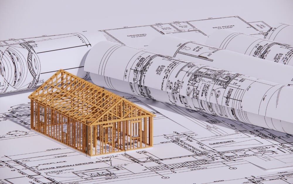
A 2D architectural drawing is a flat, scaled drawing that shows a building from one fixed view such as from above, from the side, or sliced through the middle. The five core types of 2D drawings are site plans, floor plans, elevations, sections, and details. Together, they give builders the exact sizes, materials, and layout they need to price, permit, and build a project without guessing.
What Is a 2D Architectural Drawing?
2D architectural drawing is a technical drawing that shows a building on a flat sheet using only length and width. Every line is drawn to scale, so a set distance on paper equals a set distance on site.
Drafters draw each view straight on, with no incline or depth. This method is called orthographic projection. Aalto University’s digital design guide describes 2D drawings as flat projections or cuts of a 3D object, drawn with parallel view lines. This digital design guide calls plans, sections, and elevations the most basic drawings and the step that comes before any 3D model.
This matters on a real job because a 3D image shows how a house will look, but a flat drawing shows how wide the hall is, where the beam lands, and which wall holds up the roof. Crews build from numbers, not pictures.
Small builders and remodelers rarely keep a full-time drafter on staff. Many of them use architectural drafting services to turn hand sketches and site notes into clean sheets that pass plan review.
What Are the Main Types of 2D Drawings in Architecture?
Site plans, floor plans, elevations, sections, and details make up the core. A full set adds roof plans, ceiling plans, and schedules.
Site Plan
A site plan shows the whole property from above. A site plan marks property lines, setbacks, the building footprint, driveways, trees, and utility lines. It also carries a north arrow and contour lines that show how the land slopes. City planners review the site plan first because it proves the building fits the lot and follows zoning rules.
Floor Plan
A floor plan shows one level of a building as if it were cut sideways about 4 feet above the floor and seen from the top. It shows walls, doors, windows, stairs, fixtures, and room names. Dimension strings give the length of every wall and opening.
This is the most used sheet in any set. Framers, electricians, interior designers, and home buyers all start here.
Elevation Drawings
An elevation shows one face of the building, viewed straight on. Most projects have four exterior elevations, one for each side. They show heights, roof pitch, window spots, and finishes like brick, stucco, or siding. Interior elevations do the same job for single walls such as a kitchen run of cabinets or a tiled shower wall.
Section Drawing
A section shows a vertical cut through the building, from the roof down to the footing. It reveals ceiling heights, wall build-ups, insulation, floor framing, and foundation depth. A cut line with arrows on the floor plan shows where the section plane is taken and which way you are looking.
Detail Drawings
Details zoom in on small, tricky spots at a large scale. Common ones include window flashing, stair rails, roof edges, and the joint where a wall meets the slab. Leaks and cracks tend to start at joints, so these small drawings prevent some of the costliest problems on a job.
What Other Sheets Does a Full Set Include?
| Drawing | What it shows | Who uses it most |
| Roof plan | Slopes, drains, vents, ridges | Roofers |
| Reflected ceiling plan | Ceiling heights, lights, and vents, drawn as if seen in a mirror on the floor | Electricians, ceiling crews |
| Foundation plan | Footings, slab edges, piers, anchor bolts | Concrete crews |
| MEP plans | Mechanical, electrical, and plumbing layouts | Trade contractors |
| Door and window schedules | Sizes, types, and hardware in table form | Suppliers, framers |
How Do You Read 2D Architectural Drawings Correctly?
Start with the title block, then check the scale, line weights, and symbols. These four steps tell you what you are looking at before you trust a single number.
- Read the title block: It runs along the bottom or right edge of the sheet. It lists the project, sheet number, date, and revision. Always confirm you hold the latest revision, because building from an old sheet is a fast path to rework.
- Check the scale: Each view states its own scale (see the scale table below).
- Learn the line weights: Thick lines are walls the cut passes through. Thin lines are objects seen beyond the cut. Dashed lines are hidden items or things overhead like upper cabinets. Long dash-dot lines mark center lines and column grids.
- Find the symbols: The first sheet holds a legend. It explains door swings (drawn as arcs), section markers, elevation tags, and grid bubbles.
The following table shows the common scale used:
| View | Common US scale | Common metric scale |
| Site plan | 1″ = 20′-0″ | 1:200 or 1:500 |
| Floor plan | 1/4″ = 1′-0″ | 1:50 or 1:100 |
| Elevations and sections | 1/4″ = 1′-0″ | 1:50 or 1:100 |
| Details | 1-1/2″ or 3″ = 1′-0″ | 1:5 or 1:10 |
One rule from the field: never measure a printed PDF with a ruler. Printers shrink pages to fit. Trust the written dimension, or use the scale bar if the sheet has one.
How Is a 2D Drawing Set Organized?
Sheets are grouped by trade, and each sheet number tells you what is on it. In the US, most firms follow the National CAD Standard (NCS) naming format.
Take sheet A-101. The “A” means architectural. The “1” means it is a plan. The “01” means it is the first plan sheet.
| Letter | Discipline |
| G | General |
| C | Civil |
| S | Structural |
| A | Architectural |
| M | Mechanical |
| P | Plumbing |
| E | Electrical |
| Number | Sheet type |
| 0 | General notes and legends |
| 1 | Plans |
| 2 | Elevations |
| 3 | Sections |
| 4 | Large-scale views |
| 5 | Details |
| 6 | Schedules and diagrams |
This system lets a crew find the right sheet in seconds. A callout bubble on A-101 that reads “3/A-501” points to detail 3 on sheet A-501.
Keeping that order tight is hard on a large job. A 60-sheet set holds hundreds of cross-references, and one wrong bubble sends a crew to the wrong detail. Contractors running several jobs at once often hand this work to 2D drafting services, so every sheet uses the same names, layers, and line standards.
How Are 2D Drawings Made Today?
Almost every 2D architectural drawing now starts in CAD software. Hand drafting still has a place in early sketches, but final sets are digital.
The tools fall into two groups:
- 2D CAD programs such as AutoCAD and DraftSight. Each sheet is drawn line by line.
- BIM programs such as Revit and ArchiCAD. The team builds a 3D model, and the software cuts plans, sections, and elevations from it.
The difference shows up when the design changes. Move a window in a BIM model, and every plan, elevation, and schedule updates at once. In pure 2D CAD, someone has to fix each sheet by hand. Missed updates are where mismatched drawings come from.
| Format | What it is | Best use |
| DWG | Native AutoCAD file | Editing and sharing with drafters |
| DXF | Open exchange format | Moving drawings between programs |
| Fixed, print-ready file | Permit review, bidding, field use |
When Are 2D Drawings Made During a Building Project?
Drawings start rough and get more exact at each design phase. The level of detail tells you what each sheet is safe to use for.
| Phase | What the drawings show | What they are used for |
| Schematic design | Basic layouts, room sizes, rough exterior look | Agreeing on the big idea |
| Design development | Exact sizes, materials, structure, systems | Locking the design |
| Construction documents | Full set with notes, details, schedules | Bidding and building |
| Permit set | Construction documents sent to the city | Approval |
| Shop drawings | Fabricator drawings for steel, trusses, cabinets | Making parts |
| As-built drawings | Record of what was actually built | Future repairs and renovations |
Price a job from schematic sheets, and the numbers will change once real details arrive. Firm bids belong to construction documents.
Do You Still Need 2D Drawings If You Have 3D Models or BIM?
Yes. In 2026, building departments, field crews, and suppliers still work from 2D sheets. A 3D model helps people see the design. Flat sheets tell them exactly what to build.
| Feature | 2D drawings | 3D renderings | BIM model |
| Main job | Instructions for building | Showing the look | Coordinating all trades in one model |
| Exact dimensions | Yes | No | Yes |
| Used for permits | Yes | No | Usually through sheets cut from the model |
| Best for | Pricing, permits, site work | Sales, client approval | Large, complex jobs |
Clear, matching drawings protect a budget. According to the 2018 Construction Disconnected report by FMI and PlanGrid, poor project data and miscommunication caused 48% of all US construction rework, adding up to $31.3 billion that year. The survey also found that workers spent 35% of their time, over 14 hours a week, on non-productive work like searching for project information and fixing mistakes. Unclear or outdated drawings are a direct part of that “poor project data.” Accurate sheets cut the problem at its source.
Final Thoughts
A 2D architectural drawing is the shared language of every building project. Plans, elevations, sections, and details each answer a different question, and the set only works when all of them agree. Read the title block, scale, lines, and symbols first, and any drawing set becomes easy to follow, from the first sketch to the as-built record.
Frequently Asked Questions
Q1: What is the difference between 2D and 3D architectural drawings?
2D drawings show a building as flat views with exact sizes, such as plans, sections, and elevations. 3D drawings show the building with depth, so people can see how it will look. Builders use 2D sheets for measurements and permits. Clients and sales teams use 3D views to understand a design before it is built.
Q2: What software is used for 2D drafting?
AutoCAD is the standard tool for pure 2D drafting. Revit and ArchiCAD are BIM tools that create 2D sheets from a 3D model. DraftSight and other low-cost CAD programs also open and edit DWG files. Most final sets are shared as PDFs for plan review, bidding, and use on site.
Q3: What scale are floor plans drawn at?
In the US, home floor plans are usually drawn at 1/4" = 1'-0", so a quarter inch on paper equals one foot on site. Larger buildings often use 1/8" = 1'-0".
Q4: Do you need 2D drawings for a building permit?
Yes, in almost every case. Building departments review a permit set made of 2D sheets, usually a site plan, floor plans, elevations, sections, and structural details. Many cities now accept these as PDF uploads. Rules differ by city, so check the local building department's submittal checklist before sending a set.